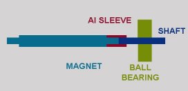
 The rotor is like Norm's version 8 design, a shortened CYL0131D from SuperMagnetMan with ends shaved down and
attached to shafts at each ends with aluminium sleeves.
The rotor is like Norm's version 8 design, a shortened CYL0131D from SuperMagnetMan with ends shaved down and
attached to shafts at each ends with aluminium sleeves.
Inspired by the efforts of NORM I decided to build my own system, something I've wanted to do (but never really known how) for many years now.
Only discovered his efforts around Christmas 2006, and spent most of January 2007 building, soldering, cutting, filing and spending money obtaining parts.
The rotor is like Norm's version 8 design, a shortened CYL0131D from SuperMagnetMan with ends shaved down and
attached to shafts at each ends with aluminium sleeves.
The ball bearings are taken from small computer fans.
As shown below, the whole rotor arrangement then fits inside a brass tube that has an inside diameter the same as the outside diameter of the ball bearings. Small pieces of fibreglass are glued to the top and bottom of the brass tube and act as formers for the coil in a similar fashion to that of Matthias (see Norms 'friends' page).
As a starting point, I'm using 100 turns of 26B&S / 0.4mm dia wire. No doubt this can be optimised later. Its a tradeoff between the time constraints inherent in inductors and the effectiveness of the magnetic force generated.
The ball bearings fit 90% of the way into the thick aluminium blocks at each end of the galvo, and the inner 10% of the bearings act as supports for the brass tube. ie the ends of the brass tube fit over the exposed parts of the bearings.
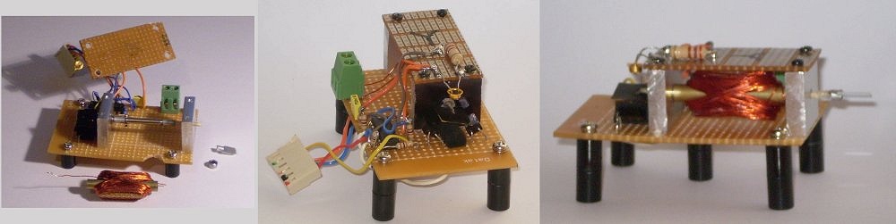 The Galvos shown above in three views. The optical PD is the black end (quite hard to see) with LN52 IR LED from
digikey illuminating the photodiodes. Since this pic was taken I've moved the photodiodes up a bit - seems to work better.
The Galvos shown above in three views. The optical PD is the black end (quite hard to see) with LN52 IR LED from
digikey illuminating the photodiodes. Since this pic was taken I've moved the photodiodes up a bit - seems to work better.The circuitry onboard is the optical PD amplifier. The green terminal attachment is for the coil drive from the power amplifier.
Mirrors are from a damaged SLR camera I picked up at a garage sale for $10. I expected to use the main mirror, but it turned out that the mirrors in the viewfinder and exposure system were more useful. One, now used for the Y galvo and seen in the pictures here, was even the perfect size.
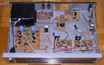
The whole arrangement fits into the gutted remains of what used to be a radio tuner, bought from an op. shop for $15.
At top left is the transformer (shielded in a box), bottom left is the power supply. The transformer gives +/- 40V which is cut back to +/- 27V using a LM317 and LM337 pair. This supplies the final power amp stage to drive the galvos. This also supplies the other circuitry after being further cut back to +/- 15V with a 7815 / 7915 pair.
At top centre is the laser, with LM317 to supply constant current. A mere 5mw red while I'm building and testing this creation. There is also one other transistor on that board for the blanking switching. Galvos are at right of the laser, arranged in the usual manner.
At top right is the interface to the computer parallel port. I'm using the DAC0832 circuit.
Bottom centre/right are the two amplifiers, based on Chan's circuit. Final power amp is a LM1875T, chosen because they can handle 20W and 4 amps, but mostly because they were readily available. Heat sinks have since been updated to fan blown computer graphics card types.
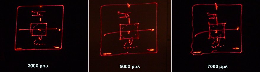
Displays are all at 8 degrees deflection. Using Norms's Lasershow program to throw data at the system at various rates, I adjusted the DRIVE control to place the circle inside the square. This can be done at faster rates, but the rest of the test pattern gets a lot worse. At these rates, the galvos start to oscillate and 'sing' if the damping is turned up more than a fraction of a percent. Its clearly a mechanical issue, not an electrical one, and is reduced substantially if I hold onto the galvos to add some mechanical damping.
Shameful admission: It might be the shaft I'm using on the rotor. In my haste to construct something and get this project up and running, I used the first thing that came to hand that fitted snugly inside the ball bearings... some TOOTHPICKS.
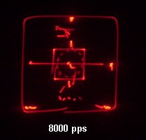
13th February 2007
After doing nothing else other than replacing the wooden toothpick shafts with some steel shafts, I now have a fairly decent ILDA image at 8000 pps.
Steel has a higher torsional strength than wood, of course, but its also heavier. The ideal material would be strong, but weigh nothing. Perhaps a ceramic shaft would be worth a try (if I knew where I might locate some).
Note also the fuzziness of the image. I scratched up my X mirror quite badly during the operation, so I'll have to replace that at some stage.